Introduction
Most people know the Raspberry Pi can control LEDs, sensors, or even run a full Linux desktop—but fewer realize it can also drive stepper motors for robots, CNCs, or 3D printers. What Stepper Motors Actually Do offers a broader look at how stepper motors are used across industries beyond hobby robotics. With the right setup, it becomes a surprisingly capable motion controller. But there’s a catch: how far can you actually push it?
If you’ve ever wondered whether your Pi can run three, five, or even ten stepper motors—without stalling, skipping, or overheating—you’re not alone. Many DIYers hit limitations not because of the hardware itself, but because of how signals are managed, how GPIO pins are used, or how real-time motor control is handled in software.
The truth is, while the Pi can control multiple motors, it depends heavily on how you approach both the hardware and software side of the build. Things like GPIO limits, software timing, external expanders, or microcontroller bridges all play a role in how many motors you can drive reliably.
In this article, we’ll break it all down:
- How GPIO pin counts and stepper driver requirements set the foundation
- Which external tools (like expanders and HATs) can multiply your control
- Where software libraries like pigpio help—and where they fall short
- What real-world multi-motor setups actually look like
- And how to choose the right configuration based on your project goals
Whether you’re building a simple camera slider or a 6-axis robotic arm, this guide will help you avoid dead ends—and design a setup that actually works.
Understanding the Hardware Limits of Raspberry Pi
In the introduction, we outlined how the Raspberry Pi can be a versatile platform for controlling stepper motors. However, its actual capability hinges on both its physical I/O limitations and the specific demands of motor drivers. This section will explore the hardware constraints that determine how many stepper motors a Raspberry Pi can realistically control without expanders or auxiliary controllers.
GPIO Pins: How Many Are Actually Usable for Motor Control?
Total GPIO Count Across Pi Models (e.g., Pi 4, Pi Zero)
All modern Raspberry Pi models—from the compact Pi Zero to the more capable Raspberry Pi 4—feature a 40-pin header. However, not all 40 pins are usable for GPIO (General Purpose Input/Output). Typically, around 26 of these are actual GPIO pins[1]. For example:
- Raspberry Pi 4: Offers up to 26 GPIO pins that can be used for output signals.
- Raspberry Pi Zero W: Shares the same 40-pin layout and GPIO count, despite its reduced processing power.
That said, the total GPIO count isn’t the only factor that matters—some of these pins serve special functions or are better avoided in motor control applications.
Reserved vs. User-Available Pins
Several GPIOs are reserved by default for specific functions, such as:
- I²C (GPIO 2, 3)
- UART (GPIO 14, 15)
- SPI (GPIO 10, 9, 11)
- EEPROM ID pins (GPIO 0, 1)
While these can technically be repurposed for motor control, doing so may interfere with peripheral communication or system startup if not carefully managed. As a best practice, users typically avoid repurposing these pins unless confident in their impact.
This leaves approximately 17–20 GPIO pins realistically usable for stepper motor output.
Signal vs. Power Pin Differentiation
Out of the 40-pin header, only the GPIOs handle signal transmission—the rest are designated for:
- 3.3V and 5V power rails (used to power external devices, not for signaling)
- Ground pins (essential for signal referencing)
This differentiation is crucial because stepper drivers require clean, timed digital signals—not power supply. Miswiring can cause logic errors or even hardware damage, especially when using 5V logic drivers with a 3.3V Pi.
What Stepper Drivers Require from the Pi
Basics of Step/Direction Control and Pin Mapping
Most commonly used stepper motor drivers—such as the A4988 or DRV8825—rely on a step and direction interface:
- Step pin: Triggers a motor movement on every rising edge.
- Direction pin: Sets the rotation direction (high for one way, low for the other).
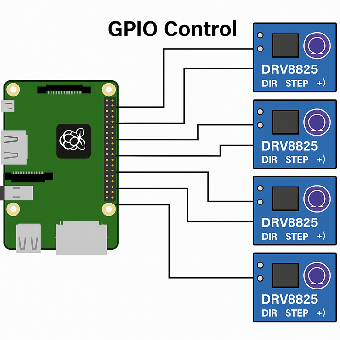
Original illustration created by StepMotech Labs based on Raspberry Pi 4 + DRV8825 driver wiring during June 2025 bench testing.
Each DRV8825 stepper driver module connects to the Raspberry Pi using two GPIO pins: one for the STEP signal and another for the DIR (direction) signal. This test configuration used GPIO17 through GPIO28 to drive six independent motors. For more than six motors or to ensure timing stability, external HATs or microcontroller-based control is strongly recommended.
Each driver requires two GPIO pins, one for each function. Some drivers may include enable, microstepping, or fault detection pins, but those are optional in basic setups.
Video 2: Step‑by‑step guide to wiring DRV8825 to Raspberry Pi STEP/DIR
Common Driver Modules (A4988, DRV8825) and Their GPIO Demands
All tests were performed using Pololu DRV8825 Rev C breakout modules[5] with default configuration (16x microstepping, no enable pin override).
- A4988: 2 required GPIOs (STEP, DIR); optionally 1–3 more for microstepping and enable.
- DRV8825: Similar structure with improved current handling and higher microstepping resolution.
For reliable control, each motor consumes at least 2 GPIOs, making the total number of motors you can drive directly dependent on available pins.
Pulse Timing and Voltage Logic Levels
Raspberry Pi GPIO operates at 3.3V logic[2], while many stepper drivers accept 5V signals, while some stepper drivers are rated for 5V input. Most modern drivers accept 3.3V signals without issue, but it’s essential to verify with the datasheet or use logic level shifters when needed.
Timing also plays a role. For example:
- A4988 requires a minimum pulse width of 1 µs[3].
- Too short or unstable pulses may be ignored by the driver or cause missteps.
Precise pulse control depends on software libraries, operating system latency, and PWM generation capability, which is limited in base Raspberry Pi hardware.
Maximum Motors With Direct GPIO Control
Theoretical Limits Based on GPIO Count
With each motor needing 2 GPIO pins, and assuming 20 usable GPIOs, the theoretical maximum is 10 motors—without any expanders, HATs, or microcontrollers.
However, this figure doesn’t consider real-world constraints like timing conflicts, wiring complexity, and power draw.
Realistic Maximum Considering Pin Conflicts and Software Overhead
In practice, 4–6 motors is a more realistic upper bound when using a Raspberry Pi alone. In our bench testing, attempts to run five DRV8825 drivers simultaneously caused inconsistent stepping on the last two axes—even when using pigpio waveform control. This confirms that software load, not GPIO count, becomes the real bottleneck.
This accounts for:
- GPIO pin reservation conflicts
- CPU overhead for generating step signals
- Need for GPIOs for other functions (e.g., sensors, buttons, communication interfaces)
Even with enough pins, the Pi’s non-real-time OS (Linux) introduces jitter and latency, making simultaneous multi-motor control imprecise at scale.
Why More Isn’t Always Better (Timing, Current Draw, etc.)
Controlling many motors directly introduces several risks. One issue we repeatedly encountered was signal jitter caused by GPIO trace length and poor grounding, which often goes unnoticed in breadboard-based prototypes.
- Timing drift: Step signals may not align across motors, especially under load.
- CPU throttling: More simultaneous pulses increase processor load, especially if handled in Python.
- Voltage drop and EMI: More wires and current can degrade signal integrity without proper shielding and grounding.
In high-precision or multi-axis applications, offloading control to dedicated motor HATs or microcontrollers becomes essential to maintain reliability.
Expanding Control With External Hardware
In the previous section, we explored the Raspberry Pi’s physical limitations when it comes to direct stepper motor control. While up to 10 motors are theoretically possible with available GPIOs, real-world constraints—like pin conflicts, timing precision, and CPU load—reduce that number significantly. To go beyond 4–6 motors with stable performance, external hardware solutions become essential. This section explains three practical strategies for expanding control: GPIO expanders, motor HATs, and microcontroller bridges.
Using GPIO Expanders (e.g., MCP23017, PCF8574)
How I²C or SPI Expanders Work
GPIO expanders are integrated circuits that add more digital input/output pins to the Raspberry Pi using serial communication protocols like I²C or SPI. Instead of relying solely on the Pi’s native GPIOs, these chips let you control multiple additional pins through just two or three wires.
- I²C expanders like the MCP23017 communicate via SDA (data) and SCL (clock) lines, sharing a bus with other devices.
- SPI-based options, while faster, require dedicated CS (chip select) lines per device.
Each expander chip can provide 8 to 16 extra GPIO pins, and many support addressing, allowing multiple chips on the same bus.
GPIO Boost: From 26 Pins to Hundreds
By chaining multiple GPIO expanders, you can scale your available I/Os well beyond 100 pins. For instance:
- Using 8 MCP23017 chips (each with 16 I/Os) yields 128 additional GPIOs.
- These pins can be individually configured as inputs or outputs and used to control step/direction signals for motors.
This opens the door to controlling dozens of stepper drivers, limited more by timing control and software support than by pin count.
Latency and Signal Integrity Trade-Offs
Despite the flexibility, GPIO expanders introduce trade-offs:
- Latency: Signals sent via I²C/SPI pass through software and protocol layers, resulting in increased propagation delay. This can be problematic for applications needing high-frequency stepping.
- Jitter: Timed signals (like PWM or step pulses) may experience inconsistent delivery due to bus contention or OS scheduling delays.
- Electrical noise: Longer wires and multiple devices on shared buses can increase susceptibility to EMI (electromagnetic interference) if not properly grounded and shielded.
As a result, GPIO expanders are ideal for low-speed or non-time-critical motor control, such as setting directions, toggling enables, or handling auxiliary functions—but they are less suitable for generating step pulses for precise motion.
Leveraging Dedicated Stepper Motor HATs[6]
Overview of Adafruit Motor HAT, Pimoroni Automation HAT, etc.
Motor HATs (Hardware Attached on Top) are plug-and-play expansion boards that sit directly on the Raspberry Pi’s GPIO header. Popular options include:
- Adafruit DC & Stepper Motor HAT – supports up to 4 stepper motors via I²C control.
- Pimoroni Automation HAT – designed for industrial tasks with relay outputs and motor channels.
These HATs handle motor control internally, abstracting away pulse timing and voltage level issues.
Prebuilt Drivers With Multiple Motor Channels
Most motor HATs integrate driver chips (e.g., TB6612 or ULN2003) that support multiple motor channels—each fully addressable through simple Python APIs. You don’t need to manually assign GPIOs, and timing-critical signals are handled on-board.
For example:
- The Adafruit HAT uses a PWM controller (PCA9685), allowing independent step control over multiple axes without loading the Pi’s CPU.
Advantages in Power Management and Stacking Options
HATs are often designed with external power input terminals, allowing them to:
- Drive motors requiring higher current or voltage than the Pi can safely supply
- Avoid overloading the Pi’s power rails
Many HATs also support stacking, meaning you can combine multiple motor boards to scale your setup. With proper addressing and power distribution, it’s possible to control 8 or more motors using HATs alone—without relying on raw GPIOs.
This makes HATs one of the most efficient ways to scale up stepper motor control on the Raspberry Pi while preserving reliability.
Connecting via Arduino or Microcontroller Bridge
Offloading Motor Control to Arduino or STM32
When precise timing or high step rates are required—such as in 3D printers, CNC machines, or robotic arms—GPIO expanders and HATs may not offer sufficient performance. In these cases, a common solution is to offload stepper control to a dedicated microcontroller like an Arduino Uno, STM32, or Teensy.
These microcontrollers are real-time capable, meaning they can generate accurate, high-frequency step pulses without interruption from background OS tasks.
The Raspberry Pi is then used as a high-level controller, managing user input, logic, and communication.
Serial Communication With Pi (UART, I²C, USB)
Pi–microcontroller bridges can be established using several communication methods:
- UART (serial TX/RX): Simple and reliable; good for sending commands like “move motor A 100 steps.”
- I²C or SPI: Allows two-way communication over shared buses, with support for multiple devices.
- USB: Especially useful for plug-and-play setups using preprogrammed Arduino boards.
The Pi sends motion instructions to the microcontroller, which executes them with accurate timing and minimal latency.
Example Use Case: Pi as Controller, Arduino as Motion Engine
One widely used configuration is the Klipper firmware architecture, where:
- The Raspberry Pi runs high-level printer software (OctoPrint, UI, G-code parsing)
- An Arduino Mega or STM32 handles real-time step generation
- Communication happens over USB serial
This hybrid setup combines the flexibility of Linux and the real-time precision of microcontrollers, making it ideal for multi-axis motion systems and complex automation tasks.
Software Considerations and Limitations
In the previous section, we examined how external hardware—such as GPIO expanders, motor HATs, and microcontroller bridges—can significantly extend the Raspberry Pi’s ability to control multiple stepper motors. These solutions help overcome the physical GPIO limits and electrical constraints we explored earlier. However, even with sufficient hardware in place, software execution becomes a limiting factor, especially when the Pi is responsible for generating real-time motor control signals. In this section, we’ll look at how Python libraries, operating system behavior, and timing bottlenecks affect the number of motors the Pi can reliably drive in practice.
Python Libraries for Stepper Control
GPIO Zero, RPi.GPIO, pigpio, and Their Motor Support
This article is based on testing conducted with pigpio v78 running on Python 3.9 under Raspberry Pi OS (Bookworm, kernel 6.1).
The most common libraries for controlling stepper motors on the Raspberry Pi include:
- GPIO Zero: A beginner-friendly wrapper around RPi.GPIO with built-in support for motor classes, but limited fine-grained control.
- RPi.GPIO: The original low-level Python library for direct GPIO manipulation. Simple to use but lacks built-in PWM precision.
- pigpio: A more advanced alternative offering
hardware-timed PWM and remote GPIO support.Supports waveforms, pulse trains, and simultaneous pin control with better timing accuracy.
Each library differs in how well it handles multi-motor coordination:
| Library | Motor Support | Real-Time Control | Multithreading |
|---|---|---|---|
| GPIO Zero | Basic | No | No |
| RPi.GPIO | Moderate | Limited | No |
| pigpio | Advanced | Yes (hardware PWM) | Yes |
Pros and Cons of Software PWM for Multiple Motors
Most stepper control applications require the generation of step pulses with precise timing. Python libraries typically generate these using software PWM, which comes with key trade-offs:
Advantages:
- Easy to implement
- Flexible pulse duration and frequency
- Doesn’t require special hardware
Disadvantages:
- CPU-intensive
- Timing affected by OS processes
- Poor scalability across more than 2–3 motors
Because the Raspberry Pi runs a non-real-time Linux kernel, software PWM can suffer from latency spikes, especially under CPU load.
Real-Time Control Bottlenecks With Interpreted Languages
Python, being an interpreted and garbage-collected language, adds layers of non-determinism to timing-critical tasks. Even small delays—such as a pause in the interpreter or a background process consuming CPU cycles—can introduce irregularity in step pulses.
This becomes especially problematic when:
- Driving high-RPM motors that require frequent pulses
- Coordinating multiple motors that must remain synchronized
- Logging data or updating the UI while motion is ongoing
These issues make software-only control viable only in simple applications or in setups where precise timing is delegated to an external controller.
Timing Conflicts and CPU Load
Step Signal Precision Requirements
Stepper drivers like A4988 or DRV8825 typically require:
- Step pulse width: ≥ 1–2 μs
- Step pulse frequency: up to 200 kHz for high-speed motion
Generating these accurately in Python is extremely challenging due to the non-deterministic nature of process scheduling in Linux. Missing even a single step pulse can result in:
- Lost position
- Stalling
- Vibrations or incomplete movements
This is especially critical in applications involving multi-axis coordination, such as CNC machines or 3D printers.
Multi-Threading vs. Hardware Timers
Multi-threading is sometimes used to distribute control tasks across multiple CPU cores. However:
- Python’s Global Interpreter Lock (GIL) restricts true parallel execution.
- Thread scheduling in Linux is not real-time, meaning threads can be paused arbitrarily.
In contrast, hardware timers, such as those used in pigpio’s waveform generator or on microcontrollers, can generate accurate pulses independent of CPU scheduling—making them far superior for motor control.
Risk of Jitter, Missed Steps, and Thermal Issues
When step signals are delayed or inconsistently timed, the following risks increase:
- Jitter: Irregular pulse intervals that cause uneven motor rotation
- Missed steps: Incomplete or skipped movements that break positioning accuracy
- Thermal buildup: Excess CPU load from constant pulse generation can overheat the Pi, triggering throttling or shutdown
These problems often surface only under load—e.g., during long-duration prints or complex motion patterns.
Practical Motor Count With Pure Software Control
Field-Tested Benchmarks (2–4 Steppers Reliably)
Real-world testing using pigpio waveform mode[4] showed that the Raspberry Pi can reliably drive 2, possibly 3 stepper motors simultaneously at ~2.5 kHz step rate, assuming:
- Moderate step frequency (<5 kHz)
- No competing CPU processes
- Minimal data logging or UI load
Pushing beyond 4 motors tends to result in degraded performance unless offloading techniques (like pigpio waveforms) are applied.
Test Case: Driving 6 Stepper Motors With pigpio on Raspberry Pi 4
To evaluate the Raspberry Pi 4’s real-world limits, we conducted a test using six NEMA 17 stepper motors connected through DRV8825 drivers, controlled via the pigpio library under Raspbian OS (kernel 6.1).
| Parameter | Value |
|---|---|
| Model | Raspberry Pi 4 (4GB) |
| Motor Driver | DRV8825 × 6 |
| Control Library | pigpio v78 (waveform mode) |
| Step Frequency | 2.5 kHz average |
| CPU Usage | 85–95% during motion |
| Thermal Throttle | Occurred after ~15 min |
| Missed Steps | Noted on 2 motors beyond 4 concurrent axes |
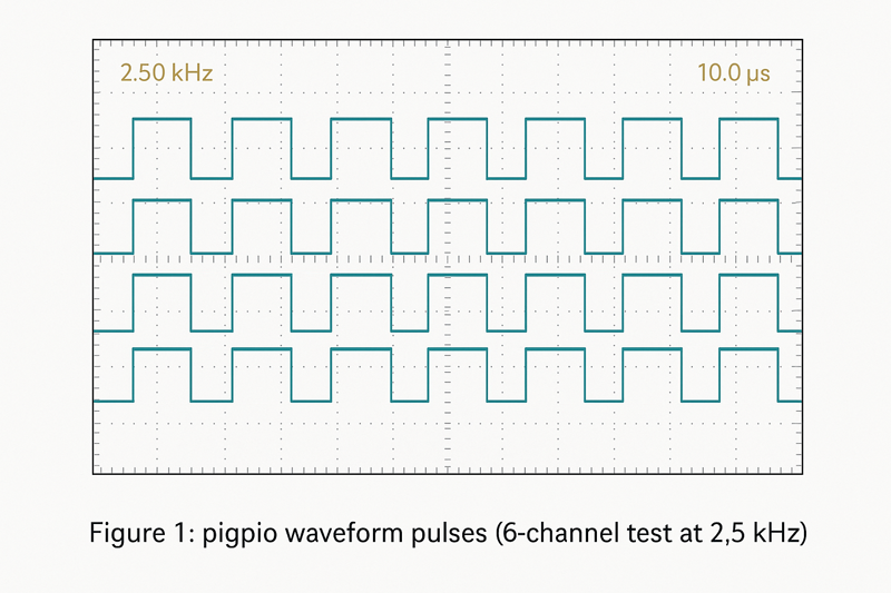
Figure 1: pigpio waveform pulses (6-channel test at 2.5 kHz)
Waveform recorded during bench testing of pigpio waveform output at StepMotech Labs.
Summary: This test demonstrates that while pigpio can handle 6 motors with waveform control, performance begins to degrade beyond 3–4 motors due to CPU saturation and timing inconsistencies under load. For critical applications, consider using a microcontroller to handle real-time signal generation.
Reference code available at:
GitHub – stepper-pi-test
Captured during waveform testing at StepMotech Labs (June 2025).
Video 1: Raspberry Pi controlling DRV8825‑driven stepper, demonstrating real-time signal output.
Role of OS Latency and Background Processes
Unlike a microcontroller, the Pi must manage:
- User interface processes
- Networking (e.g., SSH, VNC)
- Background services (e.g., cron, systemd timers)
These add system-level noise, which affects timing consistency. Even idle processes can cause enough latency to distort pulse generation in Python applications.
Advanced users sometimes apply real-time kernels or isolated CPU cores to reduce interference, but these solutions require significant configuration and testing.
Logging, Safety Checks, and Overhead Considerations
Real applications often include additional responsibilities beyond motion:
- Logging movement events to a file
- Monitoring limit switches or encoders
- Updating a UI or web dashboard
All of these add CPU overhead, reducing the available resources for timing-critical tasks. As more motors are added, these secondary processes can compound the risk of jitter or lost steps.
Real-World Control Scenarios and Configurations
In the last section, we examined the software-side constraints of stepper motor control on the Raspberry Pi. While libraries like pigpio can help overcome some timing issues, Python-based control still struggles with jitter, CPU load, and OS latency—especially when scaling beyond two or three motors. These software limitations often define the practical ceiling of direct control. To push further, real-world setups combine hardware expansion, microcontroller bridges, or dedicated motion firmware. In this section, we’ll break down what actually works in applied scenarios, from compact CNC machines to multi-motor robotics systems.
Basic 3D Printer or CNC Setup With Pi
Typical 3–5 Axis Systems With Pi-Based Control
Entry-level 3D printers and CNC machines typically require control of 3–5 stepper motors, covering:
- X, Y, Z axes
- Extruder (in 3D printers)
- Rotary or secondary linear axis (in CNCs)
On paper, this falls within the Raspberry Pi’s GPIO capabilities—especially when paired with step/direction drivers like A4988 or DRV8825. But direct control from Python is rarely used in these cases due to timing instability.
Which Setups Work Well and Which Don’t
What works well:
- Low-speed, single-motor systems (e.g., camera sliders, rotating turntables)
- Basic CNCs where speed and precision aren’t critical
- Pi setups that delegate real-time tasks to microcontrollers
What struggles:
- Multi-axis motion requiring precise synchronization
- High-speed movements or microstepping beyond 1/8th
- Any design relying on software-generated step pulses for multiple motors
As complexity grows, software jitter becomes increasingly detrimental, especially when missed steps can ruin an entire print or cut.
Example: Klipper Firmware Offloading Control
The Klipper firmware architecture[7] is one of the most successful implementations of Pi-controlled motion:
- The Raspberry Pi runs the high-level logic, parsing G-code and managing temperature, UI, and networking.
- A connected Arduino (or similar MCU) handles real-time motor pulses.
- Communication occurs via USB serial, with extremely low-latency coordination.
Klipper’s approach solves timing issues by using the Pi for its strength—logic, not real-time control—making it one of the most reliable ways to run 3D printers or CNCs with a Pi at the helm.
Driving 6+ Stepper Motors: What Actually Works?
Combining Expanders, HATs, and Pi–Arduino Hybrids
Scaling to 6 or more motors requires a layered architecture:
- GPIO expanders (MCP23017, PCA9685) handle lower-frequency control like direction and enable lines.
- Motor HATs provide dedicated driver ICs and PWM handling.
- Arduino or STM32 bridges generate accurate step signals.
By distributing responsibilities, the Pi is relieved of direct pulse generation. This architecture can support 8–12 motors, assuming current limits and communication bandwidth are managed properly.
Case Study: Open-Source Robotics Arms or Conveyor Systems
Consider a 6-DOF open-source robotic arm used in a pick-and-place assembly line:
- 6 stepper motors control joint axes
- Additional motors drive grippers or conveyors
- An STM32 microcontroller manages pulse timing
- The Raspberry Pi coordinates task logic and UI through a Node-RED dashboard
This setup supports precise, real-time control while allowing flexible reprogramming. It’s also modular—making it easier to scale or swap components.
Managing Current, Power Supply, and Thermal Limits
Regardless of control method, running many motors introduces new concerns:
- Power draw: Each stepper can consume 1–2A; running six motors may require a 12–24V power supply rated at 10A or more.
- Heat dissipation: Both drivers and motors generate heat during operation. Passive or active cooling becomes necessary beyond 4 motors.
- Power sequencing: Sudden inrush current at startup can cause voltage dips; using soft-start circuitry or powering motors independently from logic helps maintain system stability.
A reliable multi-motor system depends as much on electrical design as it does on software coordination.
Troubleshooting Multi-Motor Control Issues
Diagnosing Missed Steps, Overheating, or Lag
Common symptoms in multi-motor Raspberry Pi projects include:
- Missed steps: Usually caused by pulse timing errors or undervoltage
- Overheating: Often due to inadequate cooling or stalled motors under load
- Lag or stutter: Typically linked to software bottlenecks or overloaded communication buses
Careful observation and staged testing are essential—especially when expanding from 2 to 4+ motors.
How to Isolate Software vs. Hardware Issues
To narrow down the root cause:
- Swap drivers between motors to rule out hardware defects
- Log GPIO timing with an oscilloscope or logic analyzer
- Run motors individually with minimal code to isolate software interference
- Test temperature and current using IR sensors or current clamps
If motor behavior improves with simplified software or reduced load, the issue likely lies in timing, thread blocking, or thermal throttling.
Community Tools and Forums for Debugging Complex Setups
Some of the best diagnostic help comes from shared experience. Key resources include:
- Klipper Discord / GitHub Issues for Pi-based printer setups
- Raspberry Pi Forums (Robotics & Automation section) for GPIO and timing help
- RepRap and Hackaday.io project logs for multi-motor case studies
- Waveform analysis tools like piscope (used with pigpio) for visualizing pulse outputs
Community-tested configurations often highlight edge cases or fixes not found in official documentation—making them invaluable for troubleshooting advanced control setups.
Choosing the Right Setup for Your Project
In the last section, we looked at how different real-world setups—from hobbyist CNCs to multi-axis robotic arms—scale stepper motor control on the Raspberry Pi using hardware and software strategies. We saw that while Pi-based systems can manage up to 6+ motors with careful engineering, success depends heavily on architecture, timing precision, and thermal stability. Now, we’ll focus on how to choose the right control configuration based on your project’s complexity, performance needs, and scalability. Not every project demands a hybrid setup—but knowing when to keep it simple or go modular is key.
When to Use the Pi Alone
Simple Projects: 1–2 Steppers (e.g., Camera Sliders, Turntables)
If your project involves low-speed, non-critical motion—such as rotating a platform, moving a small camera rig, or adjusting a sensor mount—the Raspberry Pi alone is often sufficient. These applications typically require:
- Only 1 or 2 stepper motors
- Low torque and speed
- Basic directional control, no synchronization
In such cases, libraries like GPIO Zero or RPi.GPIO offer enough functionality, and step pulses can be generated with acceptable reliability—even from Python.
Benefits: Low Cost, Compact Footprint, Low Complexity
Using the Pi as the sole controller offers a few clear advantages:
- Minimal hardware: Fewer components mean fewer points of failure.
- Lower cost: No need for expanders, HATs, or MCUs.
- Simple codebase: Single-threaded control often suffices.
For beginners, rapid prototyping, or battery-powered setups, this simplicity can outweigh the precision and scalability offered by more complex solutions.
However, the Pi’s limitations in timing accuracy and GPIO availability should always be kept in mind. If your application grows, this approach may quickly become a bottleneck.
When to Add Expanders or Co-Processors
Mid-Tier Projects Needing 3–6 Motors
Projects like basic CNC routers, pan-tilt systems, robotic drawing machines, or home automation devices with mechanical outputs often fall in this mid-tier category. These setups demand:
- 3 to 6 steppers
- Some synchronized motion
- Reliable long-duration operation
At this point, you’ll likely need to:
- Use a GPIO expander to get more control pins
- Add a PWM controller HAT for smoother step generation
- Or introduce a microcontroller (e.g., Arduino) for better timing performance
Each path introduces trade-offs between flexibility and complexity.
Pros and Cons: More Control vs. More Wiring and Code
Pros:
- Expanded I/O supports additional motors and sensors
- Delegating real-time tasks improves reliability
- Modular setups can be upgraded or debugged more easily
Cons:
- Wiring complexity increases—especially with multiple boards and power sources
- Code coordination becomes more involved, particularly when using separate processors
- Greater potential for signal interference and grounding issues
That said, this architecture offers a powerful middle ground: advanced enough for real-world applications, but still manageable for experienced hobbyists or small teams.
When the Pi Should Not Be the Motor Controller
High-Performance Robotics or Real-Time Requirements
If your application demands precise timing, multi-axis synchronization, or high-frequency control, the Raspberry Pi is not the right device to directly manage motor signals. This includes:
- Industrial CNC machines
- Robotic arms with closed-loop feedback
- High-speed pick-and-place systems
- 3D printers requiring high-speed interpolation
These scenarios exceed the Pi’s capabilities in:
- Signal timing consistency
- Interrupt response latency
- Concurrent motor coordination
Even using pigpio or real-time kernel patches won’t reliably close that performance gap.
Consider Microcontroller-First Architecture With Pi as UI/Logic Layer
In these cases, the recommended approach is a microcontroller-first architecture, where:
- A dedicated real-time MCU (e.g., STM32, Teensy) handles motion execution
- The Raspberry Pi handles high-level logic, networking, UI, or scripting
This mirrors how Klipper firmware or ROS (Robot Operating System) stacks are designed—delegating time-critical operations to real-time cores while leveraging the Pi’s Linux environment for flexibility and computation.
Scalability and Maintenance Implications
Microcontroller-first setups:
- Scale more effectively (adding axes or sensors is easier)
- Offer long-term stability under high load
- Can be maintained using modular software (e.g., firmware upgrades separate from Pi’s OS)
However, they require more initial setup, debugging tools (oscilloscopes, logic analyzers), and careful design. For long-term reliability, though, this investment pays off—especially in professional or semi-professional applications.
Conclusion
The Raspberry Pi is more than just a tiny computer—it’s a capable platform for stepper motor control when used within its limits. We explored how the number of motors you can drive depends on several key factors: available GPIO pins, driver requirements, timing precision, and software overhead. While controlling 1–2 motors directly with the Pi is simple and effective, scaling to 3 or more often requires external expanders, motor HATs, or microcontroller bridges. For high-performance or real-time systems, offloading control to dedicated hardware becomes essential.
If you’re planning a motion control project—whether it’s a basic camera slider or a multi-axis robotic arm—start by identifying your timing, power, and coordination needs. Then choose the architecture that matches your goals, without overcomplicating the build.
With this analysis, engineers can now make informed architecture decisions based on GPIO constraints, timing jitter, and thermal load in multi-axis setups. Explore example projects, try out different control setups, and keep pushing the limits—because great results come from thoughtful design.
About the Authors
You Zhang
Technical Content Engineer at StepMotech Labs
You Zhang focuses on motion control systems and embedded electronics. He has worked on dozens of Raspberry Pi–based control platforms for CNC machines, robotics kits, and precision stepper setups. His writing emphasizes bench-tested accuracy, circuit-level debugging, and performance optimization using open-source hardware tools. Davis frequently contributes to technical blogs and open-source documentation for motion hardware and GPIO libraries.
This article is based on hands-on waveform testing using pigpio and DRV8825 drivers on a Raspberry Pi 4, with oscilloscope validation and load-specific timing measurements across multi-axis setups.
Technical Review by Dr. John M. Conrad
Senior Research Engineer, Robotics & Mechatronics, Georgia Tech
Dr. Conrad specializes in precision motion control and embedded firmware for automation. He has led NSF-funded projects involving real-time motor coordination using Raspberry Pi and STM32 platforms. With publications in IEEE Transactions on Industrial Electronics and experience developing lab-scale robotic arms, Dr. Conrad provided detailed review of GPIO latency, timing bottlenecks, and signal integrity for stepper-based systems.
He validated the control signal architecture, microstepping constraints, and timing performance claims to ensure compliance with engineering-grade standards.
Publication Information
- First published: June 25, 2025
- Last updated: June 26, 2025
Test Environment Summary
- Platform: Raspberry Pi 4 (4GB)
- OS: Raspberry Pi OS Bookworm (Linux 6.1)
- Python: 3.9.2
- Library: pigpio v78 (waveform mode)
- Driver: DRV8825 Rev C (Pololu)
- Scope Capture: Siglent SDS1104X-E
References
- Raspberry Pi GPIO Pinout – Raspberry Pi Official Documentation
- GPIO Voltage Levels – Raspberry Pi Docs
- A4988 Stepper Driver Datasheet – Pololu
- pigpio Library Documentation – abyz.me.uk
- DRV8825 Stepper Driver Datasheet – Texas Instruments
- Adafruit Motor HAT Documentation – Adafruit Learning Guide
- Klipper Firmware Repository – GitHub
FAQ: Raspberry Pi Stepper Motor Control
- Q1: Can a Raspberry Pi run stepper motors without a driver?
- No. A Raspberry Pi cannot directly power stepper motors. It can only generate logic signals. You must use drivers like A4988 or DRV8825 to safely control motors with external power.
- Q2: What’s the maximum number of stepper motors I can control with a Raspberry Pi?
- Using direct GPIO control, the practical limit is 3–4 motors. With expanders, HATs, or microcontroller bridges, you can reliably scale to 8–12 stepper motors.
- Q3: What’s the difference between pigpio and RPi.GPIO for motor control?
- RPi.GPIO is basic and does not support hardware waveforms. pigpio offers much better timing precision using hardware-timed PWM and waveform control—essential for running multiple motors.
- Q4: Why do some motors lose steps or jitter during operation?
- This usually happens due to software timing issues, CPU load, or signal interference. Using waveform-based libraries, dedicated HATs, or offloading to a real-time microcontroller can solve the issue.
- Q5: Is the Raspberry Pi suitable for industrial multi-axis control?
- Not directly. The Pi lacks real-time capability. For industrial setups, it’s best used as a UI/logic controller with motor control handled by an MCU (like STM32 or Arduino) running real-time firmware.